

Introductory Networking: The OSI Model
Networking theory intro, basic networking tools & foundational concepts


As I continue my cybersecurity journey I wanted to publish my notes in order to provide helpful write-ups for other learners on the same journey, with the added benefit of explaining the concepts in a beginner friendly way. I intend to break things down bit by bit and provide further clarification for learners.
This module covers the OSI Model. This section helps us learn how to understand how this model looks in practice and provides an introduction to some basic networking tools.
THE OSI MODEL: AN OVERVIEW
The OSI (Open Systems Interconnection) Model is a standardised model which we use to demonstrate the theory behind computer networking.
In practice, it's actually the more compact TCP/IP model that real-world networking is based off; however the OSI model, in many ways, is easier to get an initial understanding from.
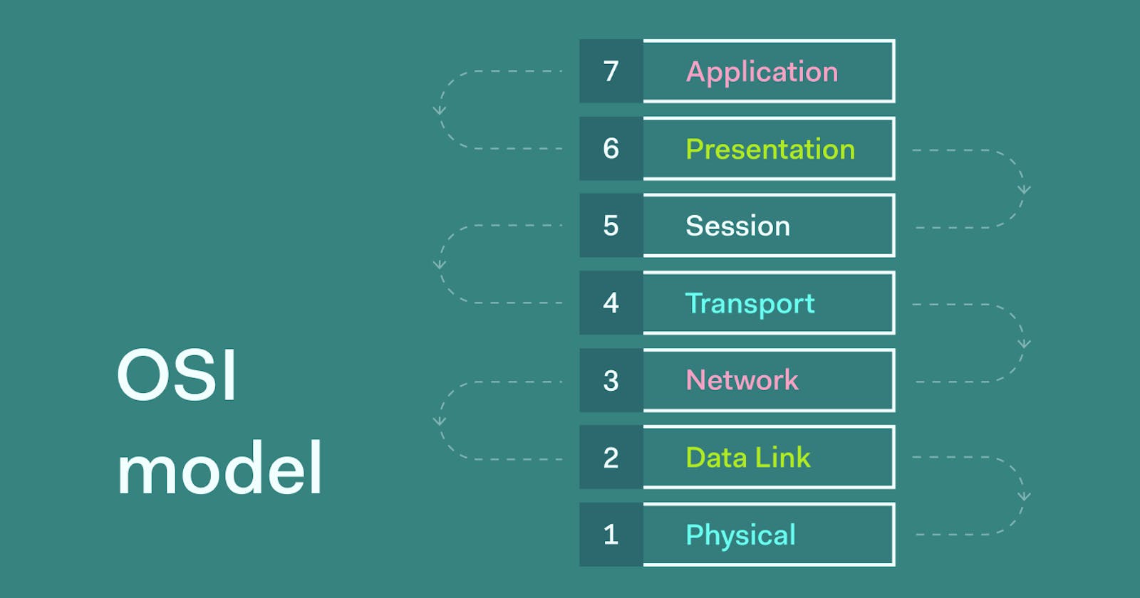
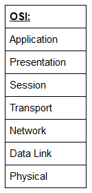
The OSI model consists of seven layers:
There are many mnemonics floating around to help you learn the layers of the OSI model -- search around until you find one that you like.
I personally favour: Anxious Pale Shakespeare Treated Nervous Drunks Patiently
Let's briefly take a look at each of these in turn:
Layer 7 -- Application:
The application layer of the OSI model essentially provides networking options to programs running on a computer. It works almost exclusively with applications, providing an interface for them to use in order to transmit data. When data is given to the application layer, it is passed down into the presentation layer.
This is the layer that the below FTP communicates with:
Glossary: FTP (File Transfer Protocol) is a standard network protocol used for the transfer of files from one host to another over a TCP-based network, such as the Internet. FTP works by opening two connections that link the computers trying to communicate with each other.
Q&A: Which layer would the FTP protocol communicate with? Layer 7
Which layer accepts communication requests from applications? Layer 7
Layer 6 -- Presentation:
The presentation layer receives data from the application layer. This data tends to be in a format that the application understands, but it's not necessarily in a standardised format that could be understood by the application layer in the receiving computer.
The presentation layer translates the data into a standardised format, as well as handling any encryption, compression or other transformations to the data. With this complete, the data is passed down to the session layer.
Q&A: Which layer encrypts, compresses, or otherwise transforms the initial data to give it a standardised format? Layer 6
Layer 5 -- Session:
When the session layer receives the correctly formatted data from the presentation layer, it looks to see if it can set up a connection with the other computer across the network. If it can't then it sends back an error and the process goes no further.
If a session can be established then it's the job of the session layer to maintain it, as well as co-operate with the session layer of the remote computer in order to synchronise communications.
The session layer is particularly important as the session that it creates is unique to the communication in question. This is what allows you to make multiple requests to different endpoints simultaneously without all the data getting mixed up (think about opening two tabs in a web browser at the same time)! When the session layer has successfully logged a connection between the host and remote computer the data is passed down to Layer 4: the transport Layer.
Q&A: Which layer tracks communications between the host and receiving computers? Layer 5
Layer 4 -- Transport:
The transport layer is a very interesting layer that serves numerous important functions. Its first purpose is to choose the protocol over which the data is to be transmitted.
The two most common protocols in the transport layer are TCP (Transmission Control Protocol) and UDP (User Datagram Protocol); with TCP the transmission is connection-based which means that a connection between the computers is established and maintained for the duration of the request. This allows for a reliable transmission, as the connection can be used to ensure that the packets all get to the right place.
A TCP connection allows the two computers to remain in constant communication to ensure that the data is sent at an acceptable speed, and that any lost data is re-sent.
With UDP, the opposite is true; packets of data are essentially thrown at the receiving computer -- if it can't keep up then that's its problem (this is why a video transmission over something like Skype can be pixelated if the connection is bad).
What this means is that TCP would usually be chosen for situations where accuracy is favoured over speed (e.g. file transfer, or loading a webpage), and UDP would be used in situations where speed is more important (e.g. video streaming).
With a protocol selected, the transport layer then divides the transmission up into bite-sized pieces (over TCP these are called segments, over UDP they're called datagrams), which makes it easier to transmit the message successfully.
Q&A: Which layer would choose to send data overTCPor UDP? Layer 4
When sending data overTCP, what would you call the "bite-sized" pieces of data? Segments
Which transport layer protocol would be best suited to transmit a live video? UDP
Layer 3 -- Network:
The network layer is responsible for locating the destination of your request. For example, the Internet is a huge network; when you want to request information from a webpage, it's the network layer that takes the IP address for the page and figures out the best route to take.
At this stage we're working with what is referred to as Logical addressing (i.e. IP addresses) which are still software controlled. Logical addresses are used to provide order to networks, categorising them and allowing us to properly sort them. Currently the most common form of logical addressing is the IPV4 format, which you'll likely already be familiar with (i.e 192.168.1.1 is a common address for a home router).
Q&A: Which layer handles logical addressing? Layer 3
Layer 2 -- Data Link:
The data link layer focuses on the physical addressing of the transmission. It receives a packet from the network layer (that includes the IP address for the remote computer) and adds in the physical (MAC) address of the receiving endpoint. Inside every network enabled computer is a Network Interface Card (NIC) which comes with a unique MAC (Media Access Control) address to identify it.
MAC addresses are set by the manufacturer and literally burnt into the card; they can't be changed -- although they can be spoofed. When information is sent across a network, it's actually the physical address that is used to identify where exactly to send the information.
Additionally, it's also the job of the data link layer to present the data in a format suitable for transmission.
The data link layer also serves an important function when it receives data, as it checks the received information to make sure that it hasn't been corrupted during transmission, which could well happen when the data is transmitted by layer 1: the physical layer.
Q&A: Which layer checks received information to make sure that it hasn't been corrupted? AND In which layer would data be formatted in preparation for transmission? Layer 2
Layer 1 -- Physical:
The physical layer is right down to the hardware of the computer.
This is where the electrical pulses that make up data transfer over a network are sent and received.
It's the job of the physical layer to convert the binary data of the transmission into signals and transmit them across the network, as well as receiving incoming signals and converting them back into binary data.
Q&A: Which layer transmits and receives data? Layer 1
ENCAPSULATION:
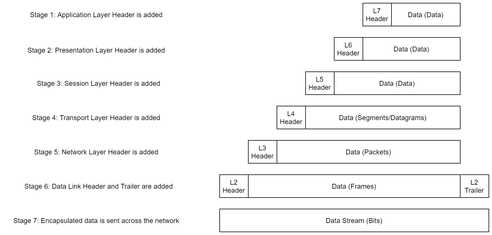
As the data is passed down each layer of the model, more information containing details specific to the layer in question is added on to the start of the transmission. (Layers 7-1)
As an example, the header added by the Network Layer(3) would include things like the source and destination IP addresses,
and the header added by the Transport Layer (4) would include (amongst other things) information specific to the protocol being used.
The Data Link Layer (2) also adds a piece on at the end of the transmission, which is used to verify that the data has not been corrupted on transmission; this also has the added bonus of increased security, as the data can't be intercepted and tampered with without breaking the trailer.
This whole process is referred to as encapsulation; the process by which data can be sent from one computer to another.
Note: ENCAPSULATES FROM BOTTOM (LAYER 2 IS LAYER 6 HERE)
Notice that the encapsulated data is given a different name at different steps of the process. In layers 7, 6 and 5, the data is simply referred to as data.
In the Transport Layer the encapsulated data is referred to as a segment or a datagram (depending on whether TCP or UDP has been selected as a transmission protocol).
At the Network Layer, the data is referred to as a packet.
When the packet gets passed down to the Data Link layer it becomes a frame, and by the time it's transmitted across a network the frame has been broken down into bits.
When the message is received by the second computer, it reverses the process -- starting at the physical layer and working up until it reaches the application layer, stripping off the added information as it goes. This is referred to as de-encapsulation.
As such you can think of the layers of the OSI model as existing inside every computer with network capabilities. Whilst it's not actually as clear cut in practice, computers all follow the same process of encapsulation to send data and de-encapsulation upon receiving it.
The processes of encapsulation and de-encapsulation are very important -- not least because of their practical use, but also because they give us a standardised method for sending data. This means that all transmissions will consistently follow the same methodology, allowing any network enabled device to send a request to any other reachable device and be sure that it will be understood -- regardless of whether they are from the same manufacturer; use the same operating system; or any other factors.
Question & Answer for Encapsulation:
How would you refer to data at layer 2 of the encapsulation process (with the OSI model)? Frames
Note: Data link layer takes the packets from the Network Layer and encapsulates them into frames.
How would you refer to data at layer 4 of the encapsulation process (with the OSI model), if theUDPprotocol has been selected? Datagram
Note: The transport layer divides the transmission up into bite-sized pieces (over TCP these are called segments, over UDP they’re called datagrams), which makes it easier to transmit the message successfully.
What process would a computer perform on a received message? De-encapsulation
Note: When the message is received by the second computer, it reverses the process — starting at the physical layer and working up until it reaches the application layer, stripping off the added information as it goes. This is referred to as de-encapsulation.
Which is the only layer of the OSI model to add a trailer during encapsulation? Datalink
Note: The data link layer also adds a piece on at the end of the transmission, which is used to verify that the data has not been corrupted on transmission; this also has the added bonus of increased security, as the data can’t be intercepted and tampered with without breaking the trailer.
Does encapsulation provide an extra layer of security**(Aye/Nay)**? Aye
Note: The data link layer also adds a piece on at the end of the transmission, which is used to verify that the data has not been corrupted on transmission; this also has the added bonus of increased security, as the data can’t be intercepted and tampered with without breaking the trailer.
The next topic covered is the TCP/IP Model. In order to see the difference between the two, check out my next post here.
As always, if you see anything I've missed or have suggestions to add, feel free to drop me a line or let me know in the comments. Happy learning!
-Mary
Sources: TryHackMe The OSI Model